TPU Flexibility Test
Evaluative report on thermoplastic polyurethane extrusion dynamics, shore hardness limits, and flexibility thresholds under varied speed and temperature settings.
Thermoplastic polyurethane (TPU) requires precise extrusion control to achieve optimal flexibility and structural integrity in FDM 3D printing. This trial report documents the performance of Shore 95A TPU across variable feed rates, extrusion temperatures, and travel speeds. The final evaluation reveals that slow extrusion speeds combined with direct-drive extrusion systems yield the most consistent elastomeric properties, preventing filament buckling and layer adhesion failures.
Extrusion Mechanics and Filament Buckling
Flexible filaments present unique challenges in standard Bowden extruder setups. Due to the high elasticity of TPU, the filament tends to compress and buckle inside the path between the drive gear and the melt zone. Direct-drive extruders minimize this distance, ensuring consistent pressure in the nozzle. The feed rate during this trial was constrained to a maximum of 20 mm/s. Increasing the speed beyond this threshold causes the filament to coil around the extruder gears, resulting in immediate extrusion failure. To avoid this, maintain a low and constant speed throughout the printing process.
Temperature Calibration and Layer Bonding
Optimal layer adhesion in TPU depends heavily on the thermal dynamics of the melt pool. The test runs evaluated temperatures from 220°C to 240°C in 5-degree increments. At 220°C, the layers demonstrate poor mechanical bonding, separating easily under manual tensile stress. The highest performance was recorded at 235°C, where the polymer chains fuse thoroughly without showing signs of thermal degradation or excessive oozing. The cooling fan was disabled for the first three layers, then set to 40% for the remainder of the print. This profile promotes robust interlayer fusion while preventing heat creep into the cold end of the extruder assembly.
Shore Hardness and Structural Elasticity
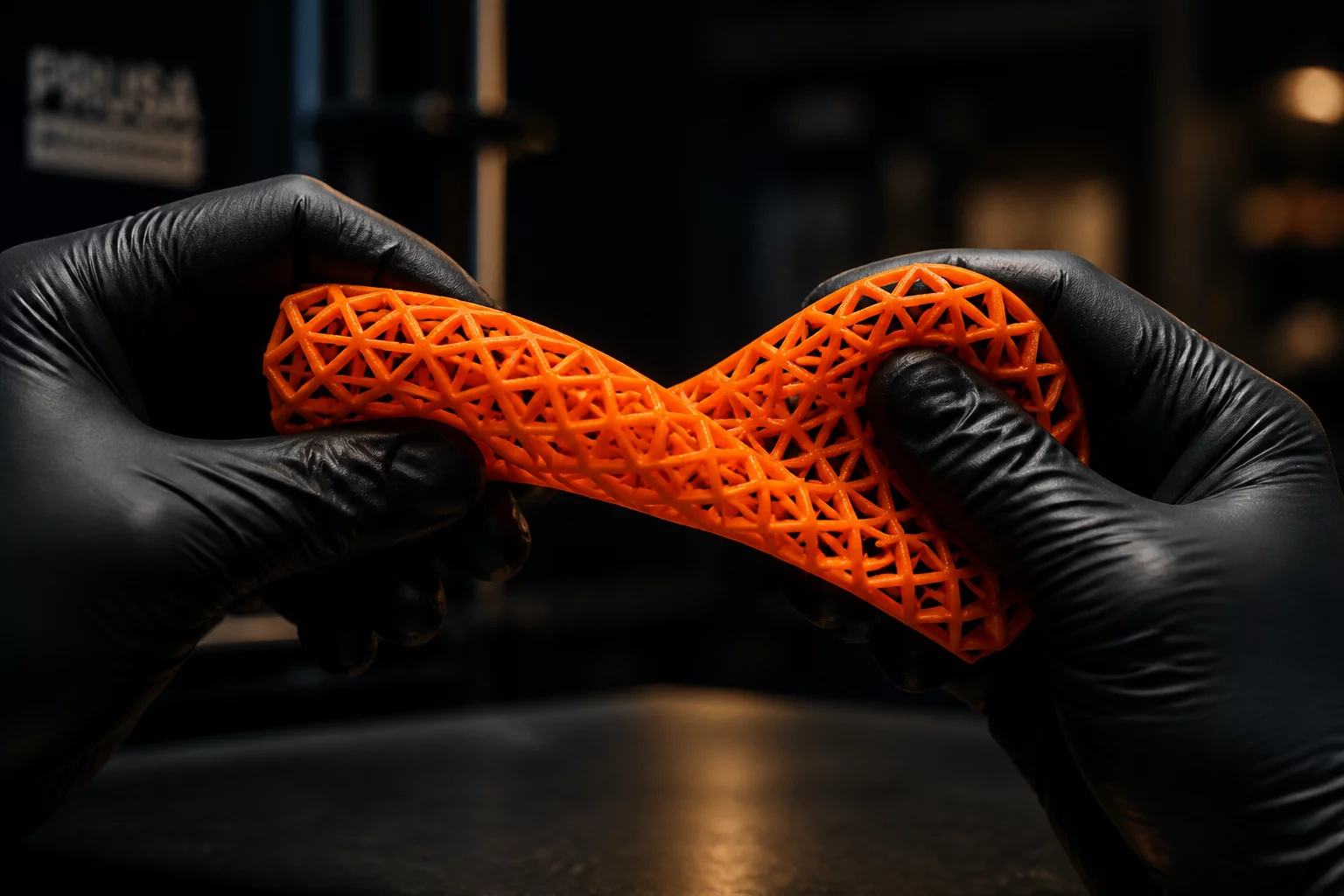
The geometry of the printed part alters its perceived flexibility. Infill density and pattern play a dominant role in the final elasticity of the component. A gyroid infill pattern at 15% density allows the part to compress and twist evenly in three dimensions. Using a grid infill pattern restricts movement along the primary axes, making the part feel significantly stiffer than its material rating suggests. Solid walls or extra perimeter shells also increase stiffness rapidly. Designers must adjust the shell count to match the target flexibility of the component.
Trial Discussion
0No comments yet. This could be your first comment.
Add to the Context
To leave a comment, please log in to your account.