SLA Support Marks Trial
An in-depth evaluation of touchpoint size, placement density, and removal techniques to minimize surface scarring on resin prints.
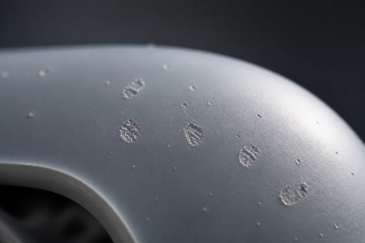
This SLA support marks trial establishes the optimal touchpoint parameters for minimizing post-processing surface defects on photopolymer resin prints. By testing touchpoint diameters from 0.2mm to 0.8mm, we determined that a 0.35mm touchpoint with a medium density configuration yields the best balance between structural integrity during printing and clean post-cure removal. Minimizing the visual impact of support structures is a critical milestone for producing end-use aesthetic components.
Core Objectives of the SLA Support Trial
The main objective of this trial was to quantify the surface deviation caused by support removal. Stereolithography (SLA) relies heavily on temporary scaffold structures to anchor overhangs and resist the peel forces generated during layer transition. However, these contacts inevitably leave residual marks, bumps, or divots that require labor-intensive sanding.
We aimed to define a repeatable configuration that minimizes post-processing time while avoiding print failures like delamination or support snapping. The test pieces featured complex curved geometries, flat angled planes, and fine detailed recesses to replicate typical production parts.
Tested Parameters and Configuration Matrix
During the trial, we evaluated three distinct variables: contact point size, support tip penetration depth, and spatial distribution density.
- Ultra-Fine Touchpoints (0.2mm - 0.3mm): Provided extremely clean separation but resulted in a 40% failure rate on models heavier than 50 grams due to structural yielding.
- Standard Touchpoints (0.35mm - 0.5mm): Offered excellent stability during peel cycles and left manageable bumps that were easily sanded.
- Heavy Touchpoints (0.6mm - 0.8mm): Caused deep surface pitting and micro-cracking upon removal, making them unsuitable for aesthetic faces.
Key Findings and Surface Quality Analysis
Removing supports prior to the secondary UV curing stage significantly reduces surface damage. When the resin is still in its green state, it possesses higher elasticity, allowing the support tips to shear cleanly at the boundary plane.
Post-cured parts exhibit increased brittleness. Attempting to snap supports off after final curing often pulls small chunks out of the model face, leaving deep pits that require epoxy filler to repair. Using flush cutters is mandatory for touchpoints above 0.4mm to prevent localized fracturing.
Optimized Post-Processing Guidelines
Based on the empirical data gathered during this trial, we recommend implementing the following sequence for all standard resin iterations:
- 1. Perform the primary IPA wash cycle immediately after print completion to remove uncured resin residue from support junctions.
- 2. Use high-quality flush clippers to cut support tips carefully, leaving a tiny protrusion rather than pulling them off.
- 3. Conduct the final UV post-curing phase once the supports have been completely detached.
- 4. Wet sand the remaining support nubs using 600-grit to 1000-grit sandpaper to achieve a perfectly uniform finish.
Trial Discussion
1James D. Sterling
07/20/2026The precision of the industrial design system described here is exactly what we need for our aerospace prototypes. The integration between technical handoff and the visual hierarchy looks seamless.
Add to the Context
To leave a comment, please log in to your account.