FDM Layer Shift Context
Analyzing mechanical faults, axis misalignment, and belt tension issues during layer transition in fused deposition modeling trials.
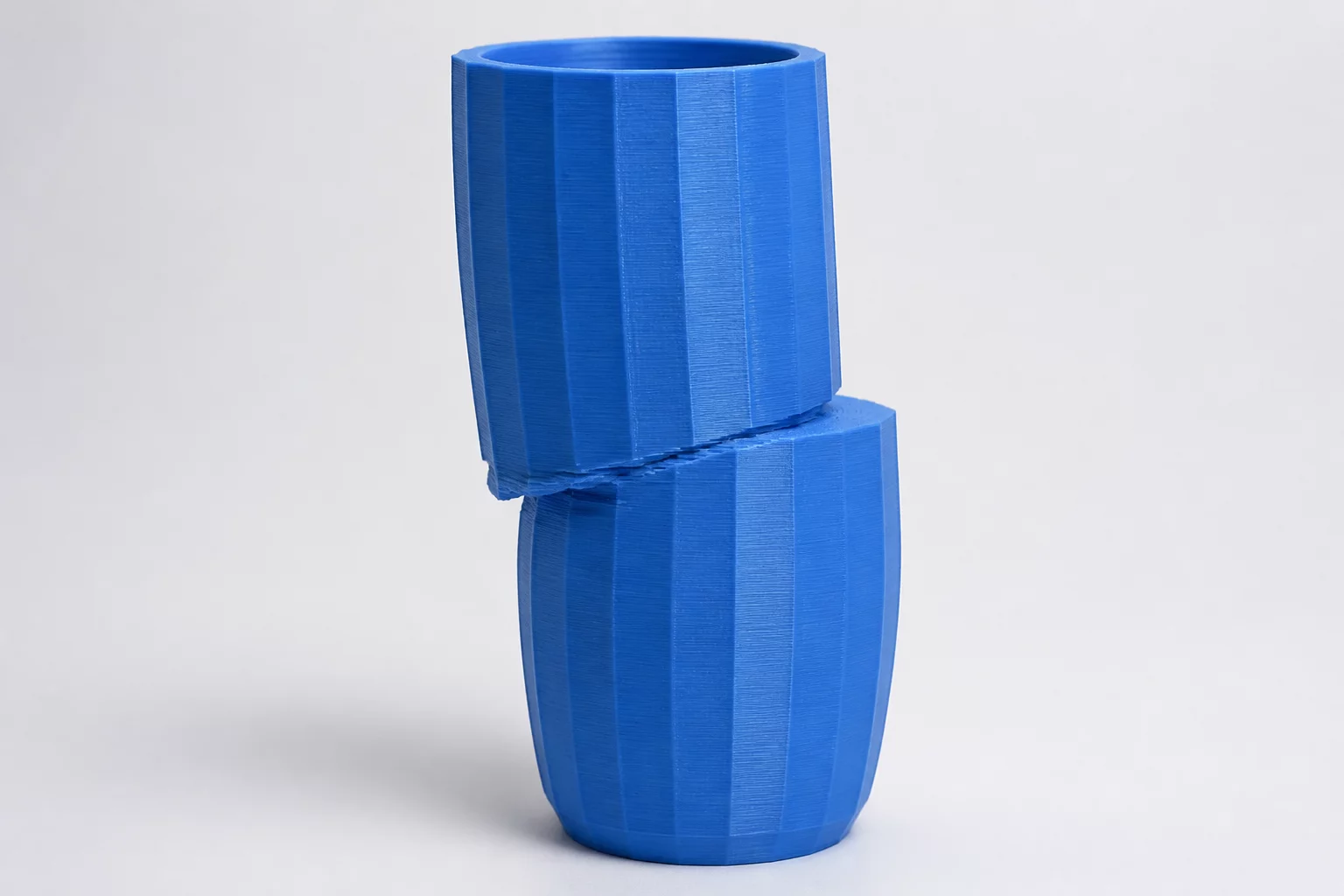
An FDM layer shift occurs when the printer's toolhead shifts away from its intended path along the X or Y axis, resulting in a misaligned, stepped appearance that typically ruins the print. This structural defect is usually caused by mechanical issues such as loose drive belts, slipping stepper motor pulleys, high acceleration settings, or physical collisions between the nozzle and curled overhangs.
Identifying the Root Mechanical Causes of Layer Shifting
When analyzing trial results for FDM prints, identifying the exact axis of misalignment is the first step toward resolution. A shift along the X-axis points directly to the print carriage assembly, while a Y-axis shift indicates problems with the print bed or the entire Y-gantry assembly. Most mechanical shifts happen when a belt skips teeth on the drive gear. This skip is often triggered by insufficient belt tension, which allows the belt to flex and jump under sudden momentum changes.
Another common culprit is the stepper motor pulley set screw. If the grub screw holding the pulley to the motor's D-shaft becomes loose, the motor shaft will spin inside the pulley without transferring motion to the belt. This results in a sudden, permanent offset in the print coordinate space, visible as a distinct shelf on the print surface.
Adjusting Slicer Acceleration and Feedrates
Extreme acceleration and jerk settings in slicer profiles like UltiMaker Cura frequently overload the physical limits of stepper motors. When a motor is commanded to change direction too quickly, it may lack the torque required to overcome the inertia of the heavy print head or print bed. This leads to lost steps, where the printer firmware assumes the toolhead is in one position while it has actually lagged behind.
Reducing the default acceleration from 3000 mm/s² to 1000 mm/s² is a proven starting point for trial iterations. Additionally, lowering travel speeds prevents violent movements that trigger mechanical skips. Heavy glass beds on Y-axis carriages are particularly prone to inertia-driven layer shifts, requiring conservative speed and acceleration values compared to lightweight build plates.
Correcting Physical Obstructions and Stepper Current
Nozzle collisions with warped print parts are a major non-mechanical cause of shifted layers. During printing, certain materials like ABS or PETG can curl upwards at the corners due to thermal contraction. If the nozzle strikes these solidified plastic protrusions during travel, the motor can stall, causing a coordinates offset.
To mitigate this, enabling Z-hop during retraction allows the nozzle to lift slightly above the print plane before moving, eliminating the risk of collisions. Furthermore, verifying stepper motor driver currents is crucial. Under-current drivers do not supply enough torque to keep up with toolhead inertia, while over-current drivers overheat and temporarily shut down to protect themselves, leading to sudden, large offsets.
Systematic Troubleshooting Protocol for Shifted Layers
To isolate and eliminate layer shifts systematically during print trials, follow these key steps:
- Inspect Belt Tension: Pluck the belts; they should sound like a low bass string and have minimal slack without being overly tight.
- Secure Pulley Grub Screws: Ensure at least one set screw aligns directly with the flat face of the stepper motor D-shaft and is fully tightened.
- Enable Z-Hop: Configure Z-hop in the slicer to a minimum height of 0.2mm to clear curled plastic overhangs.
- Monitor Stepper Temperature: Check motor temperatures during long trials; if they are too hot to touch, lower the current or install heatsinks.
Trial Discussion
0No comments yet. Be the first to leave a comment.
Add to the Context
To leave a comment, please log in to your account.